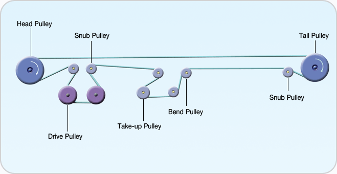
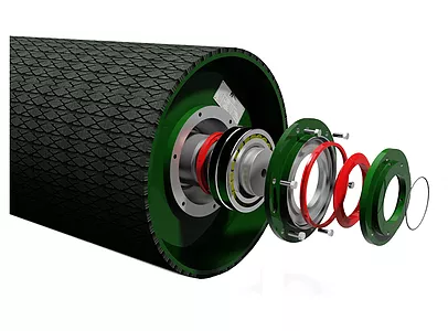
Conveyor pulleys are the main elements providing the transmission of torque from the drive and ensuring that belts remain taught. As per international standard design and manufacturing technology, there are Head Pulley , tail pulley and Bend Pulley . Conveyor pulleys are often lagged with rubber to improve the friction between the drive pulley and the belt. Conveyor Pulleys are used to transmit the drive power into the conveyor belt and as such, are subjected to the dynamic belt tension forces in a conveyor.
There are a number of different types of pulleys available for use on conveyors as well as different design parameters for pulleys serving different functions on the same conveyor.
Drive Pulley: Transmit the power with the contact force between the belt and the surface of the pulley
Snub Pulley: The purpose of the Snub Pulley is to wrap the belt further around the drive pulley to improve the transmission of the driving force, and to eliminate belt slip.
Bend Pulley: Changes the direction of a belt
Take-Up Pulley: Generally attaches to a weigh and maintains proper
Tail Pulley: Turns freely, which is located at the tail end of the belt conveyor
Special: XKTE supplies both high-quality Conveyor Components and Professional bearings.
XKTE Roller Bearing- running - in material handling bulk conveyor system.
Types and arrangement of pulley bearings
The bearings are self-aligning relative to their raceways, which means that the bearings can be 'misaligned' relative to the shaft and plummer blocks, to a certain degree. In practical terms this implies that the bending of the shaft under loaded conditions as well as minor misalignment of the pulley support structure, can be accommodated by the bearing.
1. Bearings used for conveyor pulleys are generally spherical roller bearings, chosen for their radial and axial load supporting characteristics.
2. Self-aligning Ball Bearing
Conveyor Pulley,Conveyor Drum Pulley,Belt Conveyor Pulley Shandong Xinkaite Bearing Co., Ltd. , https://www.idlerbearing.nl


Copper Mountain copper mine official contact with hydrothermal metasomatic skarn copper pyrite deposit. The ore body is like a layered output, the upper part is relatively large, and the deep part is gradually narrowed and branched, and the thickness of the ore is 2 to 33 m. The inclination angle is 32 to 82°. The upper plate is quartz diorite , which is very stable. The lower plate is quartz shale , which is stable to moderate stability, but it is soft and brittle and has poor stability due to the influence of the fault at the contact of the rock. The ore is stable and the copper grade is 0.71%. The surrounding rock contains very little copper. Pyrrhotite, pyrite ores easily oxidized under certain conditions, spontaneous combustion and agglomeration. In the past, due to open-pit mining and underground mining, the upper horizontal stratified dry filling method was used to return to the mining room. The vertical ore body of the mine is arranged in a direction of 12 to 14 m in width and 6 to 8 m in width. The height of the top column and the bottom column is mostly 4.5 to 5.5 m. The mine is filled with 80% loess and 20% stone. After the end of open-pit mining, except for the pillars of the old temple base more than zero meters have been exploited by the open pit, the remaining pillars are mainly recovered by the sublevel caving method. The structure of the subdivision method used is as shown in Fig. 1. In the deep mining, the height of the stage increased from 30m to 40m, and the inclination of the ore body slowed to about 30°, thus changing the layout of the electric raft and the structure of the stope (Fig. 2).
Figure 1 Sublevel caving mining method back to the mining column
1—filled mine room; 2—inter-column; 3—segmented electric roadway; 4—extra-pulse roadway;
5—return airway; 6—ventilated patio; 7—deep hole rock drilling chamber; 8—medium hole
Fig. 2 The section of the sublevel caving mining method with a dip angle of 30-35°
1—The lower plate goes to the electric roadway; 2—the upper section oblique electric ramp; 3—the bottom electric roadway; 4—the cutting lane;
5—cutting alleys; 6—horizontal deep hole rock drilling chamber; 7—upward deep hole rock drilling chamber; 8—slip mine; 9—loading platform;
10, 11 - extra-vehicle transportation roadway; 12 - upper plate along the vein roadway; 13 - through the vein roadway; 14 - segmentation mining boundary line
As the inclination angle of the ore body changes, the stage division and the number of segments (2 or 3) and the electric ramp arrangement are different. When the dip angle is slow, the last section of the ramp is often arranged along the strike to recover the top and bottom columns. The ramp can be 1 to 3, depending on the horizontal area and the amount of the top pillar. The distance between the ramps is 10m and the length is about 40m. The second subsection electric ramp has two arrangements of horizontal and inclined: when the ore body inclination angle is ≥40°, the horizontal electric ramp is arranged along the axial direction of the inter-column at half of the stage height, mostly double-sided funnel; When the inclination angle is about 30 to 35°, the inclined electric raft is arranged on the lower plate, the inclination angle is less than 20°, and the funnel is arranged on one side. The last section of the electric ramp is located 1 to 2 meters away from the stage transportation lane, and is mostly a single-sided funnel. When unilaterally arranged, the electric ramp deviates from the centerline of the inter-column by 1 to 2 m, so that the center of the funnel is located on the centerline of the inter-column.
Usually the above two sections are combined. Use a down-the-hole drill to drill a deep hole with a diameter of 100 to 110 mm. 28kW and 55kW electric rafts for mining.
Practice has shown that the sublevel caving method is suitable for the mine conditions, and has the advantages of wide application range, simple process, convenient construction and high production capacity. However, its accuracy is large and the total loss rate of ore is large.
The main technical and economic indicators are shown in Table 1.
Table 1 Main technical and economic indicators table (-95m middle section)
Serial number
Indicator name
unit
Quantity
Remarks
1
2
3
4
5
6
7
8
9
10
Standard ratio
Stop production capacity
Rock drilling efficiency
Deep hole
Middle hole
Deep hole collapse per meter
Ore loss rate
Ore depletion rate
Explosive consumption
Direct mining cost
Ore workshop cost
Funnel receiving ore
m/kt
t/d
Meter/table
Meter/table
t/m
%
%
Kg/t
Yuan / ton
Yuan / ton
Tons/piece
25.14
240 to 300
15~20
30~40
13
24~36
22~24
0.6
1.6
18.5
1045
The ore loss rate without residual triangle pillar is about 5%